| Tools | Analysis of geometrical outlines and shape & position tolerance |
During outline measurements with a 2D or a 3D measurement system, points (junctions) are generated which reflect the image of the test specimen as accurately as possible. The accuracy increases with the number of measured values rising, but diminishes by the width of dispersion, which is influencing each physical measurement. Generally, it applies that arbitrarily distributed points within the 2D plane can be assigned to a point, line or circular arc. Task of the outline analysis is the selection of a suitable cut-out and assignment. Only with the clear allocation of the outline sections can the parameters of the outline elements be computed.
The program WKAgraf is a development tool for the analysis, evaluation and pattern recognition of geometrical outline processes. Default is the description of an object by its base points, junctions or a point cloud, which were produced as ASCII file by measurement (e.g. CALYPSO) or mathematical modelling (e.g. ABAQUS). These data files can be imported and assigned to the geometrical basic elements point, line or circle and their parameter in such a way that they can be compared with the parameters of the sample that the user has to define for its setting of task. 3D elements are illustrated by selection of suitable cutting planes on the 2D plane. In the horizontal and vertical axis both cartesian and polar co-ordinates can be used. By combining the results from the 2D plane, the shape and position tolerances for rotationally symmetric parts can be computed.
The system is developed in a modular mode, so that also the special setting of tasks can be solved in the range of the outline analysis. Under the condition that the measurement data recording system supplies the profile, data can be analyzed for following outline elements:
Geometrical outlines:
 |
Technical representation of some selected outline elements |
| Source: OMT measuring technique, Munich |
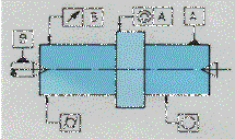
Form and position tolerances for rotationally symmetric parts according to DIN ISO 5459:
 |
Technical representation of some selected elements to the position tolerance |
| Source: OMT measuring technique, Munich |
Further computations and procedures:
· |
· |
· |
· |
· |
· |
· |
· |
· |